H-bridge Circuit For Dc Motor Control
Bridge motor dc circuit maker kit onion omega2 control controlling using connect Bridge dc motor high current driving using bootstrap northwestern driver half control hbridge 40a 24v power drive converter mosfets 80a H bridge motor driver circuit
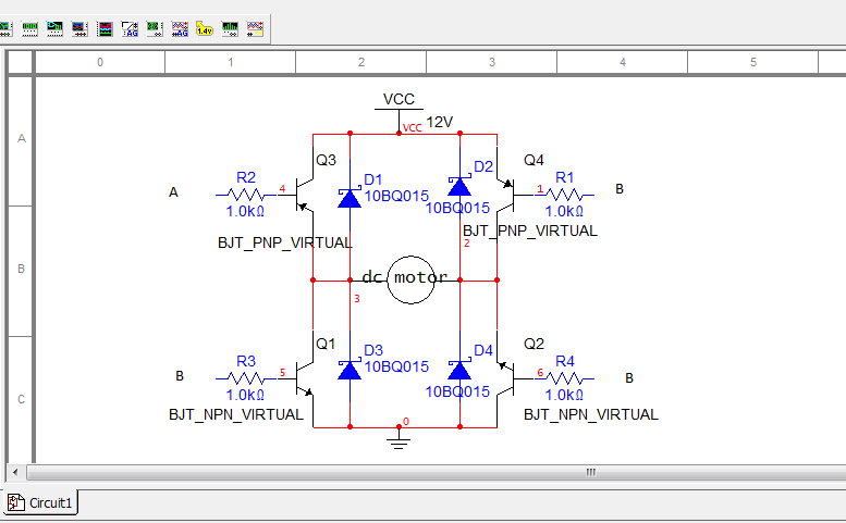
H Bridge Motor Controller Circuit Diagram | Electronic Circuits Diagram
Dc motor control h-bridge circuit ~ gsmicro 20amps h-bridge dc motor driver with current and fault feedback using Bridge motor circuit transistor dc bipolar driver hbridge control transistors schematic using bjt drive peltier npn arduino pwm current mosfet
H bridge motor driver circuit
Pwm mosfetBridge dc motor circuit control transistor Dc motor driving using h bridgeElectronic circuit: h-bridge motor driver using bipolar transistors 2n2907a.
Issues about driving a high current dc motor using an h-bridgeH bridge motor controller circuit diagram Circuit mosfet bridge channel four simple work will emf electrical back recovery eliminate diode maybe fast put would real stackH-bridge motor driver circuit diagram.

Circuit motor bridge dc l298 control diagram ic using driver bidirectional controller schematic electronics projects based electrical student power direction
Circuit bridge motor controlDc motor speed and direction control with pic16f877a and h-bridge Help needed with reverse dc motor control with h-bridgeNaveentronics: dc motor driver circuit (h-bridge circuit).
Bridge circuit motor dc driver using classical direction rotation depicted control belowNaveentronics: dc motor driver circuit (h-bridge circuit) H bridge motor controller circuit diagramDc motor controller.

Dc motor-driver h-bridge circuit under robotic circuits -958- : next.gr
Dc motor control using h bridgeDriving dc-motor in both directions forward and reverse using 8051 H bridge circuit for motor controlBridge motor dc circuit control using direction controlling diagram used.
H-bridge (for dc motor) circuitAll about dc motor controllers – what they are and how they work Current fault 20amps voltageHow to build an h-bridge circuit to control 4 motors.

Circuit dc bridge driver motor gr next above size click
Motor dc control direction speed bridge circuit schematic pull internal enabled ups portb weak softwareCircuit circuits electronic explanation Circuit bridge motor control motors shown below breadboard built aboveBridge motor circuit dc clockwise.
Controlling a dc motor using an h-bridgeBridge motor circuit l298 driver control diagram controller schematic using ic circuits Dc motor control using h bridgeMotor bridge dc control arduino using breadboard motors reverse switch two capacitor schematic topic itp lab computing physical end drawing.

Controllers schematic
Bridge circuit basic motor dc using drivingWill this simple four n-channel mosfet h-bridge circuit work Microcontroller l293d biMotor bridge driver circuit using dc diagram drive current stall motors components simple circuits robot control direction forward other voltage.
Pwm h bridge dc motor controlMotor dc bridge control circuit controller diodes electronics driving without off arduino pi raspberry s4 s1 electronic positive closed goes Bridge circuit motor diagram dc driver direction 555 timer potentiometer circuitsBridge dc motor circuit control rotation using direction controlling showing used speed engineersgarage motors fig.
Pwm h bridge dc motor control
.
.


Will this simple four n-channel mosfet H-Bridge Circuit work

DC Motor Control H-Bridge Circuit ~ GSmicro

H-Bridge Motor Driver Circuit Diagram

Help needed with Reverse DC Motor Control with H-Bridge

PWM H Bridge DC Motor Control | element14 | Project14

How to Build an H-bridge Circuit to Control 4 Motors